
Clean industrial technology
Zero Emission Flue Gas Treatment
SHU is Green Tech Egypt's patented flue gas treatment system. One water-filled absorption tower replaces the chain of filters, scrubbers and catalysts used in conventional plants, and is designed to meet the strictest European emission limits.
A revolution in flue gas treatment
Setting a new standard for flue gas emissions
In SHU, flue gases are injected at the bottom of an absorber tank filled with lime water. The water column captures dust, toxic metals and solid particles, while the lime neutralises acid gases. Three things make this effective: a very high contact surface, a small gas/liquid interface volume and a long retention time.
The process is simple and low-cost in both capital and operation. It can be installed as an add-on to existing Waste-to-Energy plants by redirecting flue gases before they reach the chimney, or built into new plants as a complete unit.
Why it matters
Cleaner air is the cost driver of Waste-to-Energy
Egypt generates more than 21.7 million tonnes of municipal solid waste every year, and only around 7% reaches an official landfill. Incineration with energy recovery reduces waste volume by about 90% and turns it into heat and power, but only if the flue gases are cleaned properly.
In a conventional Waste-to-Energy plant, flue gas treatment accounts for roughly 30% of total capital and operating costs. Meeting the EU's 2019 Best Available Techniques (BAT) limits typically requires further investment in even more complex systems. SHU was developed to meet current and future limits with a single, simpler unit.
How SHU works
From hot flue gas to clean air in nine steps
An ejector driven by water circulation creates a vacuum that draws the gases in and gives them enough energy to pass through the water head. The tower stays at atmospheric pressure.
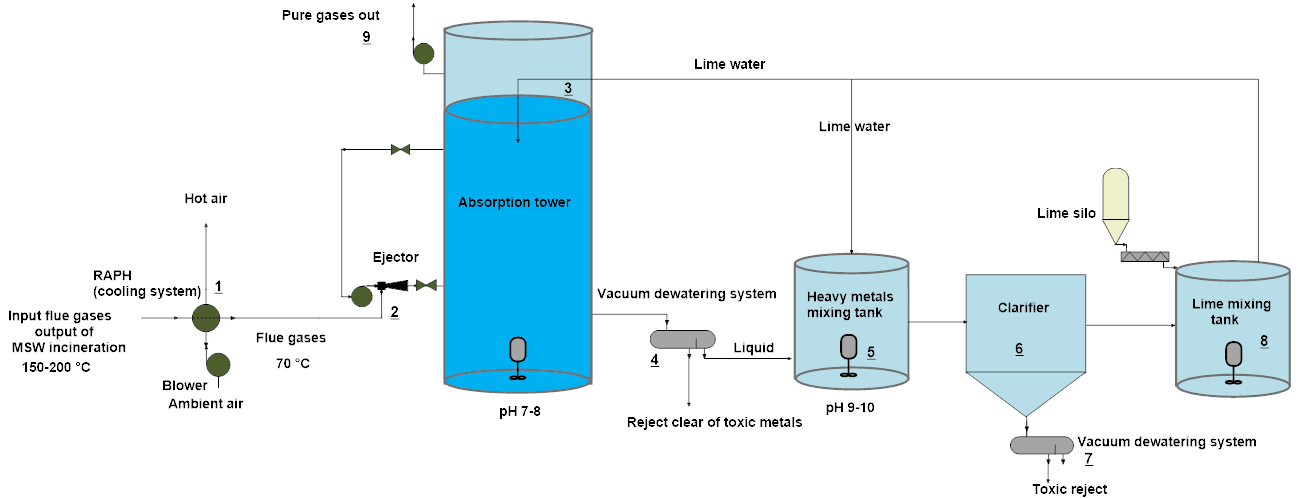
SHU process flow. Numbers in the diagram match the steps below. Scroll sideways on small screens.
- 1
Cooling
An air preheater cools flue gases from 150–200 °C to about 70 °C. The recovered hot air can be reused in the plant.
- 2
Ejector
A high-pressure water ejector mixes gas and liquid and injects the gases at the bottom of the tower.
- 3
Absorption tower
Lime water at pH 7–8 captures particles, metals and acid gases. A demister keeps droplets in the tower.
- 4
Vacuum dewatering
The reject stream is dewatered. The solid fly ash leaves cleared of toxic metals.
- 5
Heavy metals tank
Lime raises the liquid to pH 9–10 so dissolved metals turn into insoluble hydroxides.
- 6
Clarifier
The metal hydroxides settle out and are separated from the water.
- 7
Toxic reject
A second dewatering stage collects a small, concentrated toxic reject for secure disposal.
- 8
Lime mixing tank
Clarified water is dosed with fresh lime from the silo and returned to the tower.
- 9
Clean gas out
A blower in the chimney releases the cleaned gas, mostly nitrogen, oxygen, CO2 and water vapour.
The science
Gas bubbles in water instead of water droplets in gas
Conventional scrubbers spray droplets of 150–500 µm into a gas stream. SHU reverses this: the tower is filled with liquid and the gas itself becomes the contact surface. Because surface area per unit volume scales with 3/r, this raises the mass transfer rate by about 50,000 times (Fick's first law).
Conventional scrubber
Gas-filled vessel with sprayed droplets of ~50 µm and larger. Low liquid head and short contact time.
1.2 × 10⁻⁴surface area per unit volume (relative, 3/r)
SHU absorber
Liquid-filled tower with gas dispersed by the ejector, around 0.5 bar of water head and about 20 s retention time.
6surface area per unit volume (relative, 3/r) — 50,000× higher
What happens to each pollutant
Dust, dioxins, mercury and heavy metals are solid or liquid at 70 °C. They lose their kinetic energy to the water column and cannot escape the tower.
SO2 and HCl dissolve almost instantly and react with lime in under 2 seconds, well within SHU's ~20 s contact time.
NOx is absorbed as nitrous and nitric acids that lime converts into salts.
The optimum operating range is 60–80 °C. Above 80 °C more water evaporates, below 60 °C cooling costs more energy.
Key reactions with lime water
Reactivity with lime: HCl > HF > SO2 > CO2. The resulting salts leave the tower with the reject stream.
Benefits
SHU compared with a traditional system
Traditional flue gas treatment
- Several separate cleaning units to build, operate and maintain
- Existing and new plants need large additional investment to meet BAT 2019 limits
- Higher energy and chemical use, with 8–10% lime concentration
- Gases leave at 150–200 °C, so water evaporates and is lost
- Fly ash carries heavy metals and must go to a hazardous waste site
SHU
- Designed to comply with the strictest current EU limits (BAT 2019)
- Lower capital, maintenance and operating costs, with less energy and fewer chemicals
- About 1% lime and reject concentration, so a low risk of blockage
- Recovers 250–300 L of water per tonne of waste (35–40% moisture), reused within the plant
- Fly ash cleared of heavy metals can be reused in cement or asphalt, or sent to an ordinary landfill. Toxic reject is expected to fall below 10% of a traditional system's
Proven in a prototype
Independent stack measurements on the first SHU unit
The first prototype treated flue gas from a 1 tonne/day waste incinerator, using a 1 m³ absorber with a 0.2 m liquid head and a 0.35 hp ejector pump at pH 8–9. Stack gas was measured by The Expert Company in Cairo, a laboratory accredited by the Egyptian Ministry of Environment, using a calibrated TSI 6203 analyser.
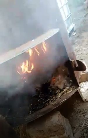
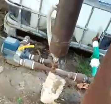
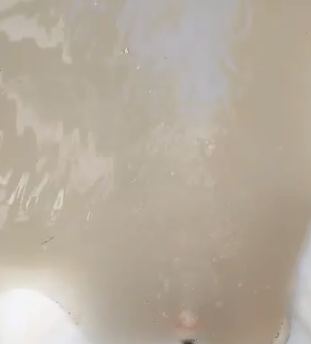
| Parameter | SHU measured |
|---|---|
| Total particulates (mg/m³) | 3 |
| CO (mg/m³) | 2 |
| NOx (mg/m³) | 1 |
| SO2 (mg/m³) | 0 |
| Temperature | < 90 °C |
| Overall efficiency | 99.6% |
The supplied SHU presentation also reports HCl at 2 mg/Nm³.
Built in Hurghada
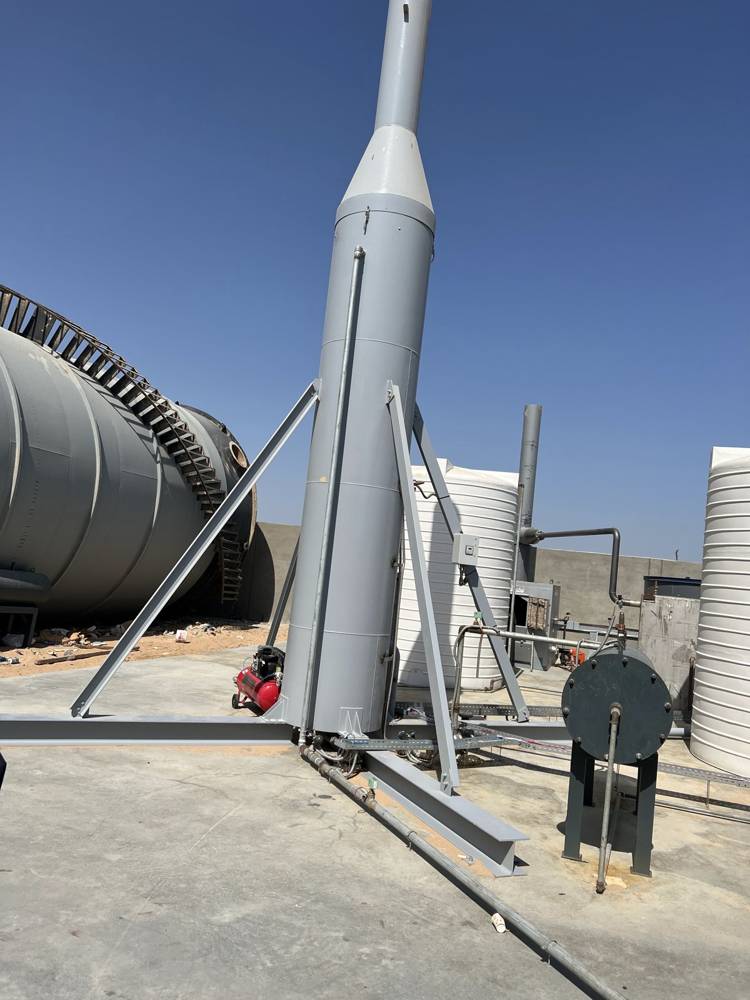
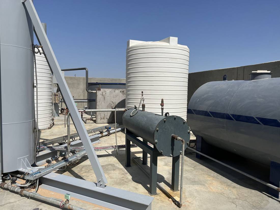
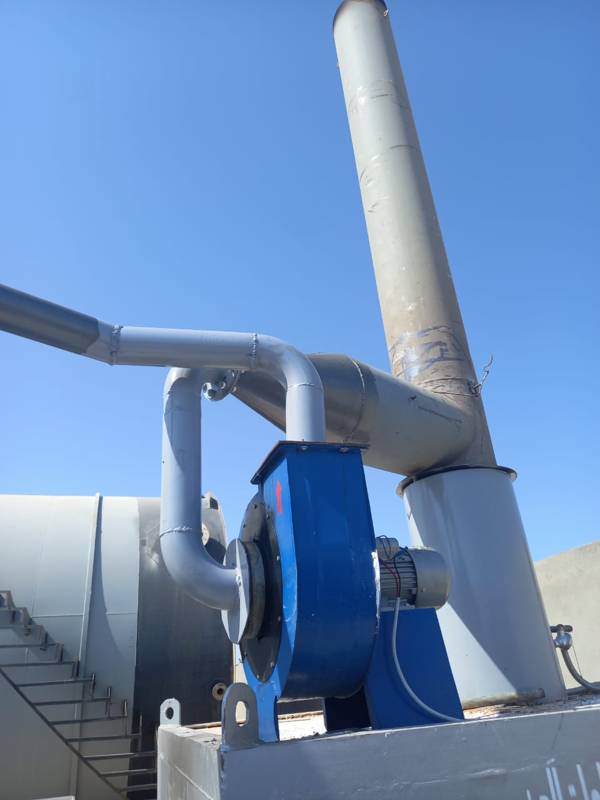
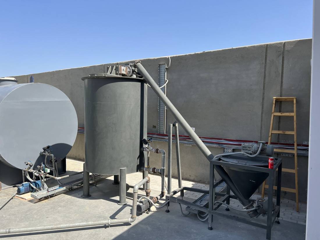
The SHU prototype plant
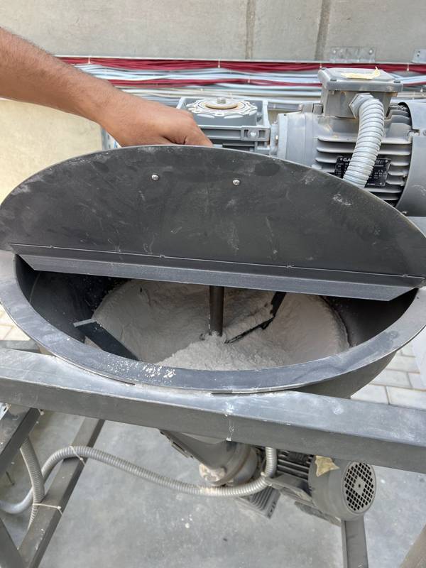
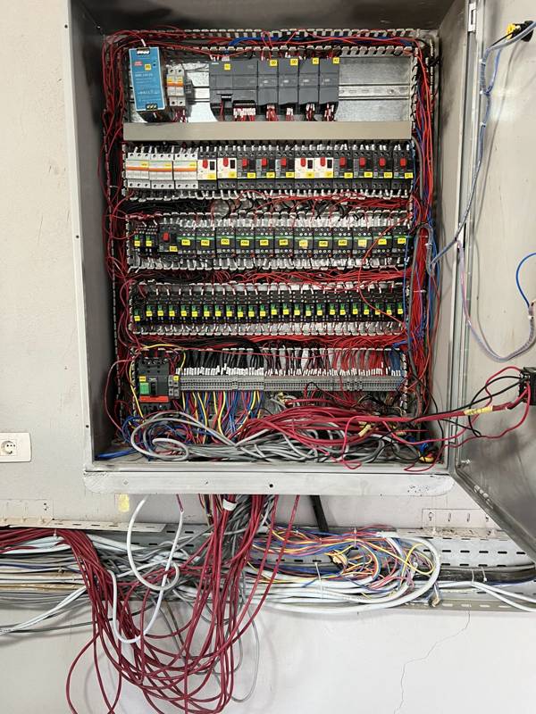
Green Tech Egypt has built a SHU prototype in Hurghada. It includes every stage of the process: absorption tower, lime preparation, process tanks, exhaust blower and stack, all run from a PLC with a SCADA control screen.
Automated control
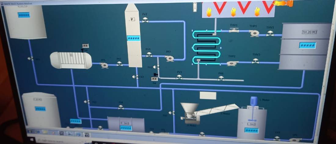
The plant is controlled by a Siemens PLC with a WinCC SCADA screen. Operators see the incinerator, heat exchanger, absorption tower, pumps, valves, lime feed and tank levels on one screen, with live readings for temperature, pressure and level.
Commercial-scale design
Expected performance at commercial scale
Calculated design values from the SHU feasibility study, distinct from the independent measurements on the first prototype.
| Pollutant (mg/Nm³) | Untreated flue gas | SHU expected |
|---|---|---|
| Particles (dust) | 4,000–6,000 | 0 |
| CO | – | 10–50 |
| NOx | 300–400 | 0–20 |
| SO2 | 450–900 | 0 |
| HCl | 600–1,500 | 0 |
| Hg | 0.3–0.5 | 0 |
| Cd + Tl | 1–2 | 0 |
| Sb+As+Pb+Cr+Co+Cu+Mn+Ni | 50 | 0 |
| Dioxins and furans (ng TEQ/Nm³) | – | 0 |
From prototype to plant
Scaling SHU
- Tested
Prototype 1
1 t/day incinerator, 1 m³ absorber. Independent stack measurements and lab tests on heavy-metal removal.
- Next
Prototype 2
2 t/day incinerator with cooling from 800 °C to 70 °C, to fix optimal tank dimensions and dosing.
- Flue gas
- 600–650 Nm³/h
- Power
- ~60 kWh/day
- Design
Add-on unit
Retrofit for existing 600 t/day incinerators, placed before the chimney.
- Flue gas
- 160,889 Nm³/h
- Power
- ~8,300 kWh/day
- Design
Complete unit
Fully integrated treatment for new 600 t/day Waste-to-Energy plants.
- Flue gas
- 160,889 Nm³/h
- Power
- ~8,500 kWh/day
The prototype was designed for a 20 s retention time. Calculations suggest the required time may be ten times shorter, so the commercial design could be smaller still. Removal of heavy metals from fly ash is supported by first lab tests and will be confirmed with further experiments.
Beyond Waste-to-Energy
One absorber, many industrial uses
The SHU absorption principle can also capture greenhouse gases and be applied to other gas-treatment processes.
Background
Understanding flue gases
Flue gas is a complex mixture created during combustion. It can include water vapour, carbon dioxide, particulates, heavy metals and acidic gases, and results from direct oxidation through incineration or indirect oxidation through gasification and pyrolysis. Many of its components are greenhouse gases.
The US EPA compares gases using Global Warming Potential (GWP): the energy absorbed by one tonne of a gas over a period, usually 100 years, relative to one tonne of CO2. Some gases with a lower GWP and shorter lifetime still contribute significantly because they are present in higher concentrations.
| Gas | GWP (100 yr) | Lifetime (yr) | 2018 (ppmv) |
|---|---|---|---|
| CO2 | 1 | 5–200 | 408 |
| CH4 methane | 28 | 12 | 1.869 |
| N2O nitrous oxide | 265 | 121 | 0.331 |
| HFC-23 | 12,400 | 222 | 0.000024* |
| PFC | 6,500–9,200 | 10,000–50,000+ | – |
| SF6 | 23,500 | 3,200 | 0.0000073* |
Source: IPCC. *Concentration in 2011.
Part of an integrated Waste-to-Energy system
Discuss SHU for your plant
SHU is part of Green Tech Egypt's ambition to run the cleanest Waste-to-Energy plant in the world. Tell us about your incinerator or industrial process and we will connect you with the right expertise.